Design of a wifi based device
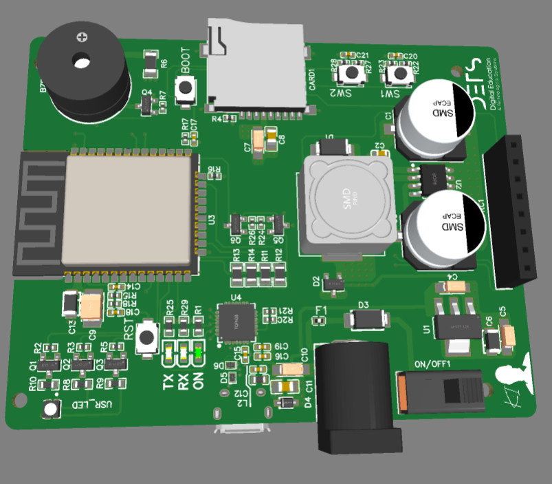
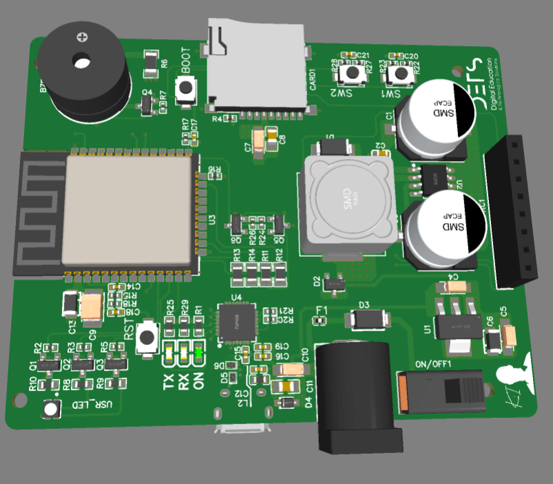
In this project, I’m going to present to you the design of a PCB I made.
For the first 4 layers PCB I made, I tried to use all I could acquire in the field of hardware design, thanks to the youtube channel of Robert Feranec who helped me so much to make this design.
Presentation of the schematic
The schematic is divided into four sections, starting from the top to the bottom, the power supply section, I used a cheap DC/DC converter to convert the 12V coming from the jack connector to a 3.3V, in the second section I put the SD card connector, an RGB led, a buzzer and a connector for placing an RFID module.
In the third section, the ESP32 and all it’s must have component to work fine, and finally the USB to UART transceiver to upload code via USB and exchanging data and serial monitoring.

The PCB
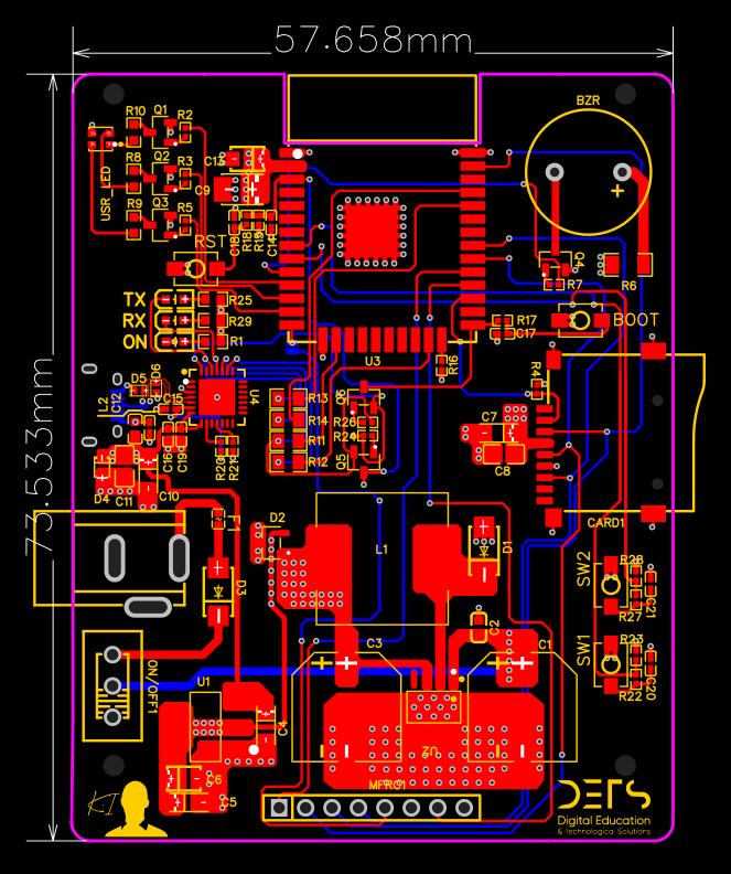
The PCB is 4 layers and it’s 58x74mm, the top and bottom layers are signals and the inner 1 and 2 are ground and power planes, I placed the power section in the bottom far from the MCU and other IC’s because of the high frequency of the DC/DC converter.


