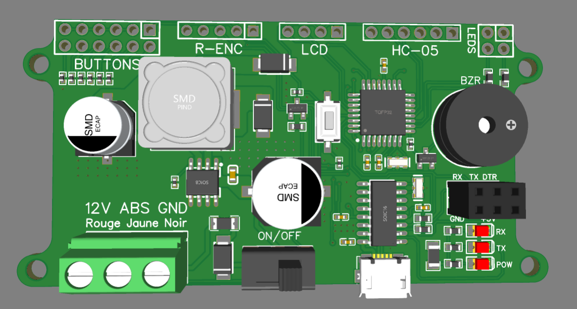
Building an Odometer for Cars Using ATmega328P-AU
In this project, I designed an odometer that can be installed in a car. The odometer interfaces with the car’s ABS encoder to retrieve speed and distance data. This article details the design and implementation process, covering the schematic and PCB design.
Overview
The heart of the odometer is the ATmega328P-AU microcontroller (TQFP32 package). The power stage includes a DC/DC converter to step down the car’s 12V supply to 5V, ensuring stable operation for the circuit. Additionally, the board features a USB to UART transceiver for serial communication and monitoring via a computer.
Tools And components
- ATmega328P-AU Microcontroller: This microcontroller is chosen for its versatility and compatibility with Arduino development environments, making it easy to program and debug.
- DC/DC Converter: The converter steps down the car’s 12V to 5V, providing a stable
- USB to UART Transceiver: Facilitates serial communication with a computer, allowing for monitoring and debugging.
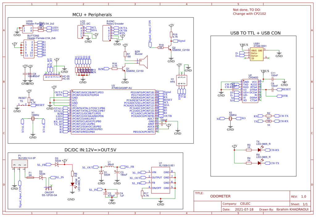
Schematic Design
- Microcontroller Section: The ATmega328P-AU is connected with essential components such as decoupling capacitors, a crystal oscillator, and pull-up resistors for the reset pin.
- Power Stage: The DC/DC converter is connected to the car’s 12V supply. The output is regulated to 5V, which powers the microcontroller and other peripherals.
- USB to UART Interface: The transceiver is connected to the microcontroller’s UART pins, enabling serial communication.
Important Connections
- ABS Encoder Signal: The signal from the ABS encoder is fed into one of the ATmega328P’s input pins, allowing the microcontroller to process speed and distance data.
- Power Supply: Ensure proper connections and filtering to maintain a stable power supply and minimize noise.
The PCB
Overview
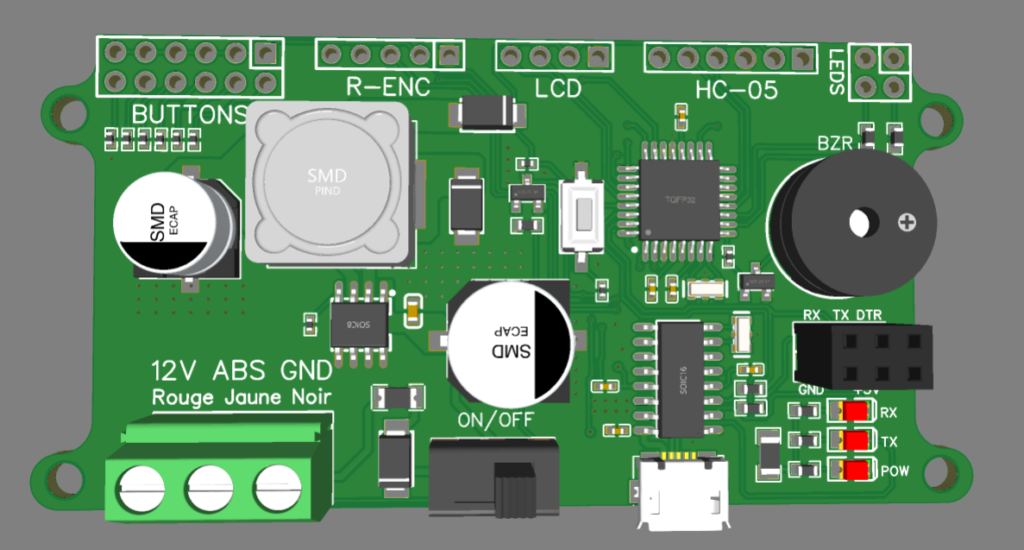
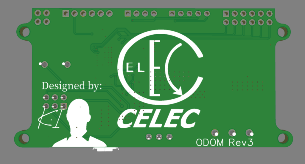
The PCB design for the odometer is a two-layer board, measuring 41x82mm. It includes four screw holes for secure mounting. The layout is carefully planned to minimize electromagnetic interference (EMI).
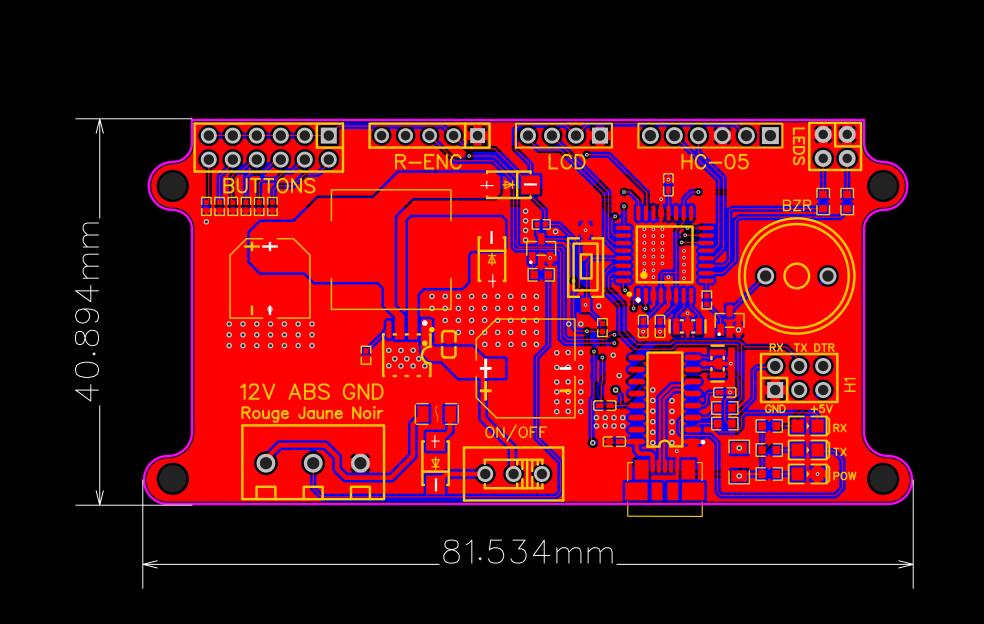
PCB Layout
- Power Section: Located at the bottom right of the board, the power section includes the DC/DC converter and associated components. Placing the power section separately helps in isolating noise from the digital components.
- Digital Section: Positioned on the right side, the digital section houses the ATmega328P-AU microcontroller and the USB to UART transceiver. This separation from the power section helps to reduce EMI.
- Ground Plane:
- A continuous ground plane is used to further minimize EMI and provide a stable reference for all components.
- Trace Routing:
- Critical signals, such as those from the ABS encoder, are routed carefully to avoid noise and ensure accurate data processing.
- Mounting Holes:
- Four screw holes are included to securely mount the PCB in the car.
PCB Design Considerations
- Minimizing EMI:
- Separation of power and digital sections.
- Use of decoupling capacitors and proper grounding.
- Thermal Management:
- Ensuring adequate cooling for the DC/DC converter, especially in the automotive environment.
- Signal Integrity:
- Careful routing of critical signals to avoid noise and ensure reliable operation.
Assembly and Testing
Soldering Components
- Soldering Tips:
- Use a fine-tip soldering iron and quality solder.
- Ensure all components are properly aligned and soldered to avoid connection issues.
- Initial Power-Up:
- Connect the PCB to the car’s power supply and check for correct voltage levels and stable operation.
Flashing the Firmware
- Programming the ATmega328P-AU:
- Use an Arduino-compatible programmer to flash the firmware onto the microcontroller.
- Ensure proper connections and follow the programming steps.
Testing the Odometer
- ABS Encoder Signal:
- Connect the ABS encoder signal to the PCB and verify data reception using serial monitoring.
- Serial Communication:
- Use a terminal program on a computer to monitor and debug the data from the odometer.
Conclusion
This project demonstrates the design and implementation of an odometer for cars using the ATmega328P-AU microcontroller. By carefully designing the schematic and PCB layout, and considering factors such as EMI and thermal management, a reliable and functional odometer can be achieved. This project not only enhances understanding of microcontroller-based design but also provides a practical solution for automotive applications.
- Documentation:
- ATmega328P Datasheet
- DC/DC Converter Specifications
- Further Reading:
- “Automotive Embedded Systems Handbook” by Nicolas Navet and Francoise Simonot-Lion
- “Practical Electronics for Inventors” by Paul Scherz and Simon Monk
